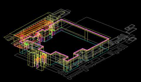
Learning Sites logo

HOW  WE  BUILD  A  RENDERED  3D  MODEL

An Example from the Northwest Palace of Ashur-nasir-pal II at Nimrud

Interactive Publication Prototype


Several software programs and intermediary steps are needed in the process, which moves from the 2D architectural plan, to a 3D model, to the application of textures and colors to the surfaces of model, and then to the generation of a fully rendered image (or conversion to virtual reality). Northwest Palace Throne Room (rendered with wireframe overlay)


Northwest Palace of Ashur-nasir-pal II, Nimrud -- Plan


Our starting point, a typical plan, here showing the excavated remains and conjectured parts of the Northwest Palace of the Assyrian king Ashur-nasir-pal II at Nimrud (present-day Iraq; 9th c. BCE). 

We began our modeling and rendering in the area of the Great Northern Courtyard.


Detail of the plan of the Northwest Palace of Ashur-nasir-pal II, Nimrud
We began working on the area around Entry D, leading from the Great Northern Courtyard into the Throne Room ('B').


3D wire-frame model of the Northwest Palace of Ashur-nasir-pal II


The plan drawing is scanned, then it is imported into any of several programs to begin the process of turning the 2-dimensional (bit-mapped) information into a scalable, accurate, 3-dimensional (vector-based) computer model.  The computer model itself can be constructed using a CAD (Computer-Aided Design) program, where lines on the scanned plan become scalable lines (vectors) that the computer can understand as having lengths and endpoints.

One of the steps in the conversion from a flat image into a 3-dimensional computer model in CAD software is giving a height (z dimension) to each element in the plan (x and y dimensions).  The image above is a wire-frame diagram showing the outline of each edge in the computer model; that is, each line represents the edge of a 3-dimensional polygonal solid.  A floor, ground, or ceiling must also be built and positioned.


3DStudioMax view of Northwest Palace plan


The same information can be obtained through a sophisticated 3D modeling and rendering program, like 3DStudioMax.  The image above shows the CAD-based information as a 2-dimensional plan again, which is used as a reference for orientation early in the rendering process

The 2-dimensional plan is then converted into a 3-dimensional image, using the same software.  This intermediary step is necessary so that the software now understands that we would like to work in an accurate and precise 3-dimensional environment for the next set of processes.


3DStudioMax view of extrusion process


In the image above, yellow has been chosen to indicate walls, red for other structural members, green, brown, and purple for specific elements around Entry D that will become important later in the process.  The colors are arbitrary and are only chosen to make elements in the computer model easier to read.

In this view, the computer model can be freely rotated along any axis to allow the renderer to study the model from all angles to be sure all the elements have been correctly modeled, that there are no overlapping elements that would make rendering difficult, and that there are no gaps in the polygons that would appear as holes in the final rendering.


Northwest Palace simple shaded model
To assist in studying the process, occasional simply shaded models are generated.  Such views allow us to understand the underlying geometry to be sure that, for example, no normals (faces that are to receive textures later) have been flipped or polygons omitted.

During these tests, the 3D model is exported from and imported into several different programs to be sure the results are as expected.


Northwest Palace simply textured model


Once the model is progressing satisfactorily, pieces can be viewed in a more realistic manner. Textures are now assigned to each surface (each polygon or group of polygons) of each element in the computer model.  Texture mapping, as the process is called, assigns a color, a pattern, a photograph, or a drawing--any range of image types--to each polygon.  The texture map is then given attributes, such as, whether it can throw shadows, whether it is transparent or reflective, whether it is bumpy or smooth. 

Also, the texture map must be accurately scaled to match the real-world surface type that it is simulating; the coordinates of the texture map must also be accurately positioned so that horizontals stay horizontal and verticals stay vertical.

Since the view above was taken from the working window of the rendering program it does not yet look 'real' or finished. 


Below are several image types that can be used as texture maps and various types of views of the Palace that we rely upon to be sure that what we are building matches what the original may have looked like as closely as the evidence permits.

Great Northern Courtyard facade drawing

Great Northern Courtyard facade photograph

Great Northern Courtyard distant overview photograph

Ethnographic evidence

Williams College winged genius relief


Entry D - textured with cameras in place


From 
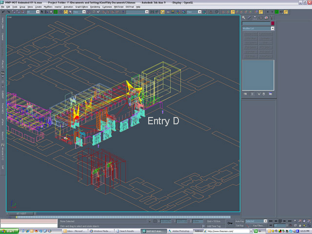
within the rendering program, we can then position and define the lights and cameras.  Lights of various sorts make the now-textured surfaces visible with the proper reflectance and shadowing.  Cameras are surrogate eyes--viewpoints corresponding to places from which higher resolution renderings can be generated; they are also helpful for studying the model from key angles or at important locations.
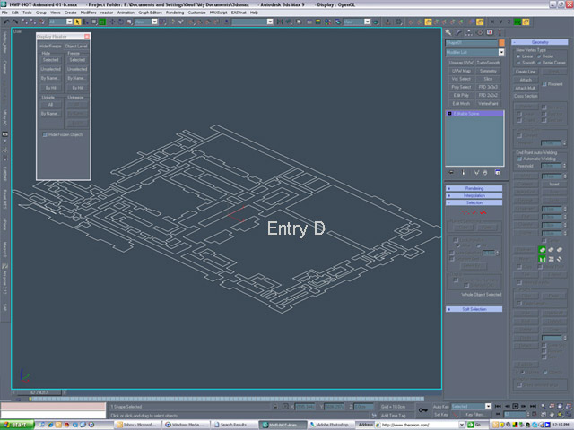
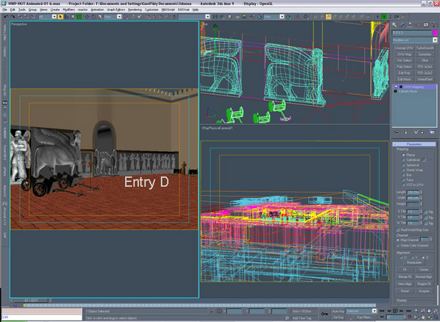
We are still within a modeling and rendering program, so there is no free movement within the computer model, as there is in a virtual reality environment.  However, within the rendering program, we can set up a path along which a camera can be set to move.  We then set the speed that the  camera moves along the path (akin to walking speed, for example) and the length in seconds that the camera should move.  That tells the software how many individual frames it must render (which could easily number several hundred or thousand). The computer then begins to render each frame in sequence.  When the sequence is played back it provides a smooth animated flythrough of the model.
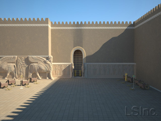
Once all the parameters have been set and tested, the computer model can be exported out to VRML (the Virtual Reality Modeling Language) for viewing in real time, allowing users to feel as though they are walking through the Palace.  Users may walk up to the reliefs or the sculpture and study them closely, as if visiting the real site or the museum that holds the material.


Entry D - test of various types of texture maps


This image is a progress rendering of Entry D output from the sequence of events outlined above.   The walls have been textured to simulate weathered mudbrick; the lamassu and some reliefs have had photographs of the in-situ remains used as their texture maps; other reliefs have had drawings of their scenes used as texture maps (the drawings were colored and bump mapped to begin to simulate the original bas-reliefs).


This rendering is farther along in the process.  The textures on the surfaces are more realistic, as the photos and drawings have been replaced with accurately colored images to simulate original conditions; the interior room has been completed, and there is a figure for scale.

Note, that at this stage, the 3D modeling of the lamassu has not been completed.


This is a nearly final rendering of the same entryway.  Now the elements have all been fully modeled, doors and people have been added and the result is getting close to what the site may originally have looked like, except for one major omission (there is no color on the carvings).


This is one of the reliefs from the Williams College Museum of Art collection showing what it may have looked like with its original colors restored (based on pigment tests we undertook on this and other reliefs).

prepared by Learning Sites, Inc.

rev. March 13, 2007